FAQs
Please note: this guide is intended for advanced Linux users only.
The BB-400 as standard ships using Raspbian (Debian) Linux with additional Brainboxes software to manage the device. Brainboxes default software image allows you to easily install new programs from the expansive Debian Linux repositories and get a more flexible setup on the device, however, some users may wish to install a more minimal system specifically tailored to their use-case in order to minimise the potential surface area and overhead on their device.
The embedded Linux build system « Buildroot » allows you to build a customised Linux system image with your specific requirements as defined by a configuration file. The Raspberry Pi Compute Module 3 as used in the BB-400 can be targeted by Buildroot and with some alterations can work well on the BB-400 as an alternative to Brainboxes default Raspbian software image. This guide will take you through building an image for the BB-400.
Prerequisites
To create and install a Buildroot-based image, you will need:
- A desktop Linux system (a virtual machine is acceptable). This guide is written with Debian/Ubuntu in mind, but other distributions should work with some trial and error.
- A good Internet connection.
- A micro-USB cable (used to connect to the BB-400 in Flash mode).
- The BB-400 GPIO pin configuration file (
dt-blob.bin), available to download here. - On a Debian based system, you will need the following packages installed:
bc bison build-essential flex git libncurses-dev rsync unzip wget
Downloading the Buildroot sources
As of writing the current long-term-stable (LTS) version of Buildroot is 2024.02.5, and this guide will be using those sources throughout. The same configuration should apply to newer versions of Buildroot too.
In your Linux terminal run the command:
git clone --depth=1 https://gitlab.com/buildroot.org/buildroot.git -b 2024.02.x
to acquire the Buildroot sources with Git.
Configuring Buildroot
cd into the buildroot directory and run make raspberrypi3_64_defconfig to create a base configuration file targeted to the Raspberry Pi 3 family of devices. If successful, the message configuration written to /home/bb/buildroot/.config should be printed (the directory structure for your file will be different but it’s successful regardless).
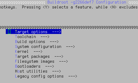
Next we need to specify some changes from the base configuration file. The easiest configuration editor to use is menuconfig. Run make menuconfig to start the editor and you should get a screen looking like this:

From here, use the arrow keys and <ENTER> to navigate the menus and <SPACE> to toggle options on/off.
Toolchain
This setting is optional but highly recommended. By default Buildroot will download and compile the entire GCC toolchain which can take a long time. We can speed this up by using a pre-compiled toolchain instead.
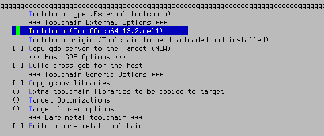
In the Toolchain menu, set « Toolchain Type » to « External Toolchain ». The option « Toolchain (ARM AARch64 13.2.rel1) » should automatically be selected after applying this setting:

After this setting is applied, use the right arrow key to Exit back to the main menu.
System configuration
In this menu you can change settings such as the hostname, init system type, default shell, locale (language) settings. The recommended settings to change are:
- System hostname: Set this to your hostname of choice, though the BB-400s come with BB400-ABCD as standard (ABCD being the final 4 characters in a MAC address). If deploying on a large scale you may wish to leave this as a placeholder, as this can be changed later via Linux commands.
- Init system: Set this to « systemd ». Systemd is the de-facto standard init on modern Linux systems and most programs aim for compatibility with it. It also has some useful programs built-in.
- Root password: Give the device a password for logging in as the root user. By default, root has no password in Buildroot.
/bin/sh: (Recommended) Set this to Bash. Bash is the most widely used Linux shell and retains compatibility with older scripts, though has slightly less performance than the default Busybox /bin/sh. - Default local time: Set this to the timezone you normally configure on your Linux systems.
- Path to the users tables: File path (relative to the buildroot directory) to a file containing the users to be created (excepting root) on the device. See Buildroot documentation for the format of this text file.
Kernel
The kernel used is the Raspberry Pi fork of the Linux kernel, as used on the standard Raspbian distribution.
In-tree Device Tree Source file names: Set this to only broadcom/bcm2710-rpi-cm3, as we do not need the device tree files for other devices in the Raspberry Pi 3 family.

Target packages
This area is where you can select which applications to install on your image. Your requirements will vary and you are encouraged to browse through each section and select what you need for your design. Note that Buildroot does not include any sort of package management system, so all applications required must be built via this system, they cannot be built then installed to the device at a later time.
The core of Buildroot is designed around an application called « Busybox ». Busybox is a collection of common Linux utilities, and Buildroot will include a good default list of which utilities to build. You should be able to leave the Busybox configuration settings alone unless there is a specific Busybox application you require, which is covered later in this guide.
Some recommended applications to install are:
Hardware handling:
Firmware: linux-firmware: WiFi firmware: Redpine rs9113: Firmware file for the WiFi module used on the BB-400.
avrdude: Tool to flash Arduino devices, including the BB-400’s I/O and PMU micro controllers.
dbus-broker: Required for NetworkManager.
Libraries:
Crypto: openssl support: used for SSL/TLS access across a wide array of applications.
Networking applications:
network-manager: NetworkManager is used on the BB-400 by default and is a very capable program for managing Ethernet and WiFi settings. Enabling « nmtui support » and « nmcli support » is also recommended.
openssh: The standard Linux SSH client and server, used to securely access the device over a network. Enabling « client », « server », « key utilities » is recommended. Disabling « use sandboxing » is recommended, as issues have been observed with this enabled.
wireless-regdb: Contains configuration for legal WiFi power/channel configurations by country.
wpa_supplicant: Required if you plan to use the WiFi on the BB-400. Enabling « Enable autoscan » and « Enable support for the DBus control interface » is also recommended in the wpa_supplicant sub-menu. If you plan to use the WiFi on a WPA2-Enterprise network make sure to also enable « Enable EAP ».
Shells and utilities
gnupg2: Utility for encrypting, decrypting, signing and verifying files.
System tools
docker-cli and docker-engine: Enable if you plan to use Docker applications
Text editors and viewers
nano: Widely-used, user-friendly text editor.
Filesystem images
These options can largely be left at the default, but the « exact size » parameter should be increased. By default it is set to 120MB which is very small, the BB-400 devices ship with 32GB of storage. You should set this value to a higher capacity with a trade-off between storage capacity and image flashing speed.
Configuring the kernel
After we have finished the general Buildroot setup, use the arrow keys to Exit from the menuconfig program and when prompted to save changes, select yes. You may wish to save this configuration elsewhere, if so run cp .config name_of_new_file.buildroot.config (with your own filename of choice).

The next step is to configure the Linux kernel.
The default Raspberry Pi kernel is well-configured, but the drivers used by the Wi-Fi module are not compiled in. As such, we need to edit the kernel configuration to add them in ourselves.
Run make linux-menuconfig to enter the Linux kernel menuconfig interface.
Under Device Drivers, then Network device support, then Wireless LAN look for Redpine Signals Inc devices then Redpine Signals Inc 91x WLAN driver support. Press <SPACE> to enable these drivers in the kernel.

Once this is set, Exit back to the main menu and select yes when prompted to save your configuration.
Configuring Busybox
As mentioned earlier Buildroot is built around a program called Busybox. While the default configuration has a good amount of programs included you may wish to include more of them in the build. If you are happy with the defaults that Busybox provides, you can skip this step. Otherwise, run make busybox-menuconfig to enter the Busybox menuconfig interface.
In the Busybox menuconfig interface, use the same controls as the Buildroot and Kernel menuconfig interfaces to enable the options that you require. When you have finished and save your changes, you can copy this Busybox configuration file (located in output/build/busybox/.config) to somewhere else for use in future builds. To ensure that Buildroot uses your custom Busybox configuration file in future, set the option Target packages: BusyBox configuration file to use to point to to the custom configuration file then save the Buildroot configuration again.
GPIO device tree blob configuration
Lastly we need to copy the GPIO configuration binary blob to the boot partition on the device. As the BB-400 does not use the standard GPIO layout for the peripherals, a binary blob with the configuration data must be provided, called dt-blob.bin. While this could be copied to the boot partition of the BB-400 after it has been flashed, it’s easier to copy it automatically.
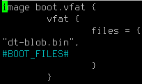
From the Buildroot top directory, edit the file board/raspberrypi3-64/genimage.cfg.in.
Before the #BOOT_FILES# line, add a new line with just "dt-blob.bin",« :

Save that file, then edit the file board/raspberrypi3-64/post-build.sh. This file is a script which runs after Buildroot has finished building the filesystem.
Add the following code at the end of the script and save the file:
# Copy dt-blob.bin to BINARIES_DIR to allow it to automatically be included in genimage
cp ${CONFIG_DIR}/board/raspberrypi3-64/dt-blob.bin ${BINARIES_DIR}/
Lastly copy the dt-blob.bin file downloaded earlier (from Prerequisites) to the directory board/raspberrypi3-64/.
Building the system
After all of the above has been completed, we can build the system. If you are not already in the main Buildroot directory, move to it. Run make, optionally with the -j parameter to run multiple jobs in parallel, for a multi-core machine.
Depending on your system, this will take roughly an hour to build a final image.
Flashing the image
After the `make` commands have finished, you will find a file called `sdcard.img` in the `output/images/` directory which is ready to be flashed to the BB-400.
The procedure for flashing the device can be found here. The requirements for the manuf_info can be skipped, and replace the Public image with the newly-generated sdcard.img file. After booting the device back up after the flashing operation, the LEDs will not start to blink as mentioned in the guide.
After booting, connecting an Ethernet cable should bring up the interface and the device should acquire a DHCP address. If you installed OpenSSH, you should be able to login as a non-root user with the newly acquired address. Alternatively you can login as root using a serial (TTL, 3.3v) cable connected to the device.
With the case open, to the bottom-left of the Compute Module 3 there is a 6-pin TTL serial header. The FTDI product TTL-232R-3V3 is designed for this header, or alternatively you can use (at your own risk) your own 3.3V TTL cable. From left to right, pin 1 is GND, Pin 4 is RxD and Pin 5 is TxD.
Using WiFi
A setting must be changed to enable the WiFi module. The first is to set the operating mode of the module to « client » mode.
To do this, first run (as the root user, or via sudo if you have that installed/configured) mkdir /etc/modprobe.d/rsi.conf. In the file, add the line options rsi_usb dev_oper_mode=1 to inform the rsi_usb to load in client mode.
The WiFi module on the BB-400 does not automatically start, instead the GPIO line connected to it must be enabled first. The GPIO line can be activated with the commands:
echo 25 > /sys/class/gpio/export
echo out > /sys/class/gpio/gpio25/direction
echo 1 > /sys/class/gpio/gpio25/value
This must be done on every boot, so adding it to a startup script is recommended.
Using the I/O ports
The I/O ports are available to be used with the ASCII protocol over the serial port /dev/ttyACM0.
PMU Arduino to Compute Module pinouts
The table below lists the connections from the Power Management Unit (PMU) ATmega16M1 chip (U6) to the Raspberry Pi Compute Module. Direction is from the Point of View of the Pi:
| Name | Description | PMU Pin | Direction | CM GPIO Pin | HIGH | LOW |
|---|---|---|---|---|---|---|
| CM_RUN_HOLD# | High to disable CM_RUN | 1 | CM_RUN <= CM | 36 | – | – |
| PM_RST_EN | High to enable PM_RST# to PMU | – | PM_RST# <= CM | 37 | – | – |
| PM_RST_CM# | Reset PMU, Through AND gate to PM_RST# to PMU | 31 | PM_RST# <= CM | 6 | – | – |
| CM_HALTING | High when CM is shutting down | 1 | PMU <= CM | 21 | CM shutting down | CM running |
| CM_HALT_REQ | Assert to request CM to shut down | 30 | PMU => CM | 27 | Request shutdown | – |
| CM_RUN | Hold low to prevent CM starting up | 17 | PMU => RUN | – | Allow Start | Prevent Start |
| CM_UPS_ALERT | ‘UPS Backup Mode’ signal to CM | 15 | PMU => CM | 26 | UPS Alert | – |
| PM_CS# | SPI select from CM | 2 | PMU <= CM | 8 | – | – |
| SPI0_MISO | SPI MISO | 8 | PMU <= CM | 9 | – | – |
| SPI0_MOSI | SPI MOSI | 9 | PMU => CM | 10 | – | – |
| SPI0_SCLK | SPI SCLK | 28 | PMU <= CM | 11 | – | – |
For the SPI connection CM PI is master, PMU is slave. In Linux the location of the SPI is /dev/spidev0.0.
Controlling the LEDs
Messaging the PMU through the SPI connection can be used to control most of the LEDs on the front of the case. The LEDs are connected to the PMU as they are on the same PCB. 4 Outputs of the PMU are multiplexed to set LEDs on and off:
STATELED0 (PMU PIn 29), STATELED1 (32), STATELED2 (13), STATELED3 (14)
| Label Name | Schematic | Description | SPI command code |
|---|---|---|---|
| A | LED503 | A – Nominally User Logged in | 0x50 |
| B | LED530 | B – Nominally NFC | 0x51 |
| C | LED523 | C – Nominally Serial | 0x52 |
| D | LED532 | D – Nominally Bluetooth | 0x53 |
| WEB | LED510 | Wireless LAN WEB | 0x54 |
| LINK | LED501 | Wireless LAN LINK | 0x55 |
| PRECHARGE | LED512 | Power State – Precharge | – |
| RUNNING | LED521 | Power State – Running | – |
| UPS ALERT | LED513 | Power State – UPS Alert | – |
| STOPPING | LED531 | Power State – Stopping | – |
The power state LEDs are not addressable as the PMU state machine controls them.
Also, there are direct connections between the CM and LEDs as follows, these are all outputs from the CM: they are connected to the CM as they are on the same PCB
| Name | Description | CM GPIO Pin # |
|---|---|---|
| ETH1LED_RED | Ethernet 1 RED LED | 38 |
| ETH1LED_GREEN | Ethernet 1 GREEN LED WEB Connection | 39 |
| ETH2LED_RED | Ethernet 2 RED LED | 40 |
| ETH2LED_GREEN | Ethernet 2 GREEN LED STATUS 100Mb | 41 |
The RED and GREEN LED on an Ethernet port can not be both on at the same time, the is a function of the led circuitry. If both LEDs are set to on, neither will turn on.
The IO Lines are controlled by the Arduino, in order to know the LED state, but still be able to completely change the Arduino firmware, the status of the DIO leds are connected to the CM as follows:
| DIO STATUS | Schematic | CM GPIO Pin # | CM GPIO Pin # (hex) |
|---|---|---|---|
| 0 | UDI0 | 20 | 0x14 |
| 1 | UDI1 | 22 | 0x16 |
| 2 | UDI2 | 23 | 0x17 |
| 3 | UDI3 | 24 | 0x18 |
| 4 | UDI4 | 12 | 0x0C |
| 5 | UDI5 | 13 | 0x0D |
| 6 | UDI6 | 18 | 0x12 |
| 7 | UDI7 | 19 | 0x13 |
