FAQs
Contents
- PE-405 Eval Kit Quick Start
- Powering your PE-405 & Performing a Self-Test
- What is a Broadcast Storm?
- PE-405 & PE-505 LED’s
- Creating a Test Environment
- Monitoring Power Consumption
- Restoring Power Consumption Track
- PE-405 Eval Kit Migration to your System
- Creating an RJ45 to MicroMatch Ethernet Cable
- External LED States
- Designing the PE-505 into your System
- Device Testing & Results
- PE-205
- PE-405
- PE-415
- PE-505
- PE-515
This FAQ document aims to guide you through the setup and configuration of our Pure Embedded range of switch products, giving detailed instructions and guidance throughout.
PE-405 Eval Kit Quick Start
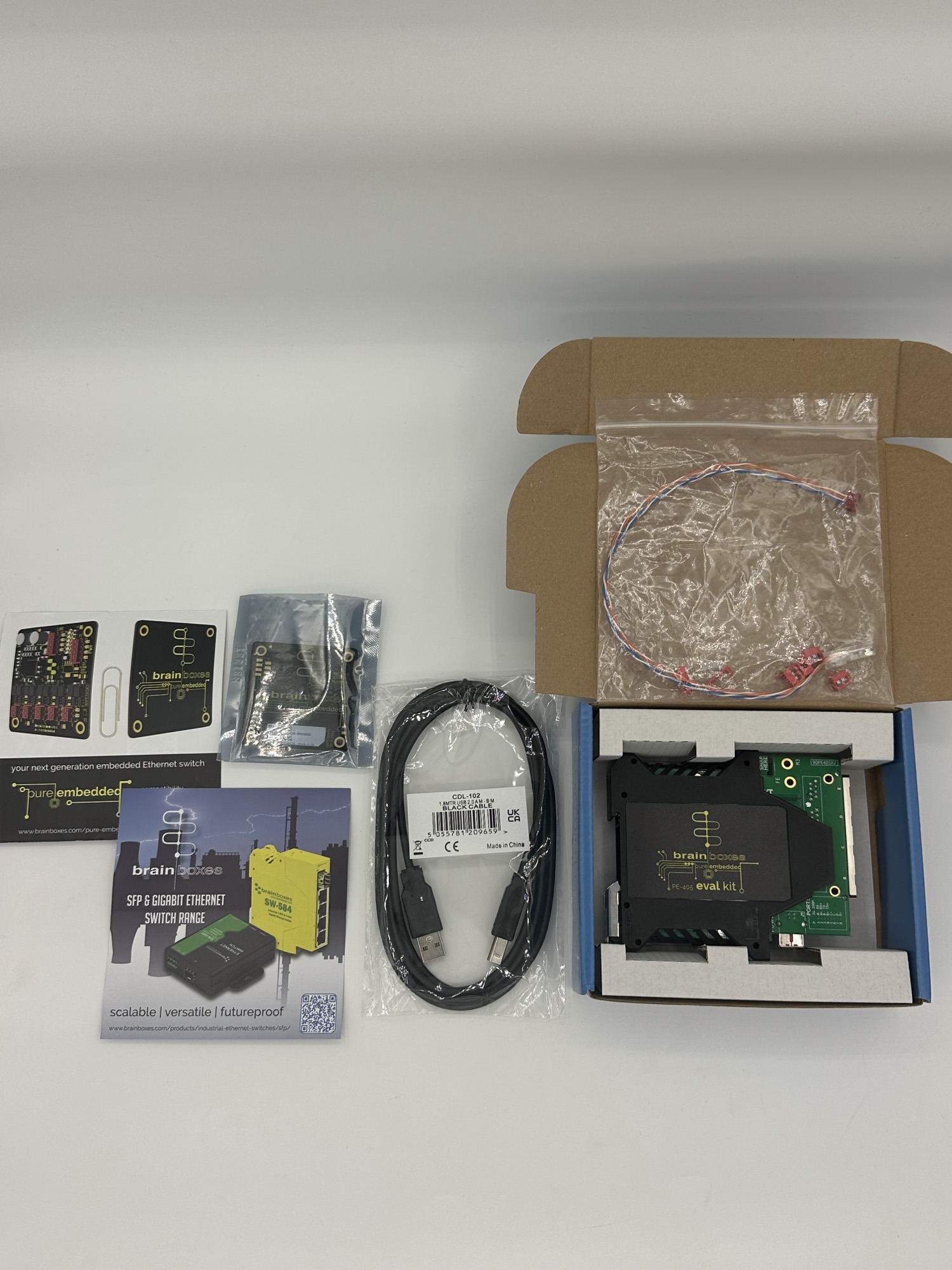
Upon opening the PE-405, you will be greeted with the following items:
- Pure Embedded Industrial 5 Port Ethernet Switch (PE-505)
- Mating board (breaks out all ports and functionality to RJ45 or usable headers)
- USB A to USB B cable
- MicroMatch to RJ45 adaptor cable
- 4 x MicroMatch 4-way headers
- 1 x MicroMatch 8-way header
- Brainboxes product documentation
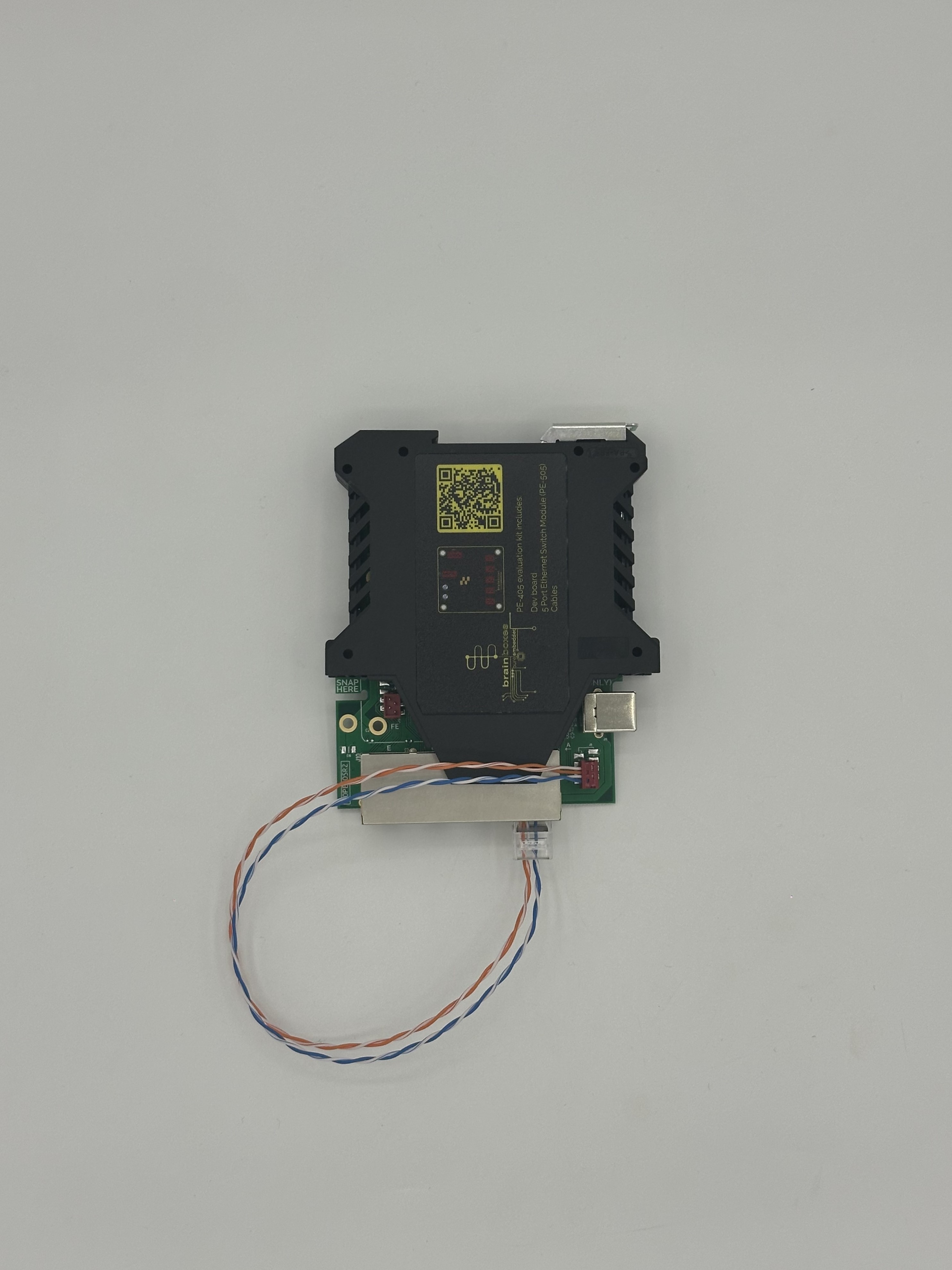
Removing the PE-405 from the box you will notice the PE-505 is attached to the evaluation board via the MicroMatch headers on each product, for now whilst we test the boards functionality, we will keep the two products connected to each other.
On the PE-405, there are 4 x Ethernet RJ45 Magjacks and 1 x MicroMatch Ethernet port. Access to the 4 Ethernet ports can be done using a standard RJ45 Ethernet cable. To access the MicroMatch port (Port A) locate the RJ45 to MicroMatch cable included in the box and connect it to the MicroMatch header located above the USB power connector on the evaluation board (as shown in the image below):
Warning
It is vital that prior to continuing with the steps outlined below regarding the self-test, please ensure that there are no active network connections between any of the PE-405’s Ethernet ports and your local network.
Powering your PE-405 & Performing a Self-Test
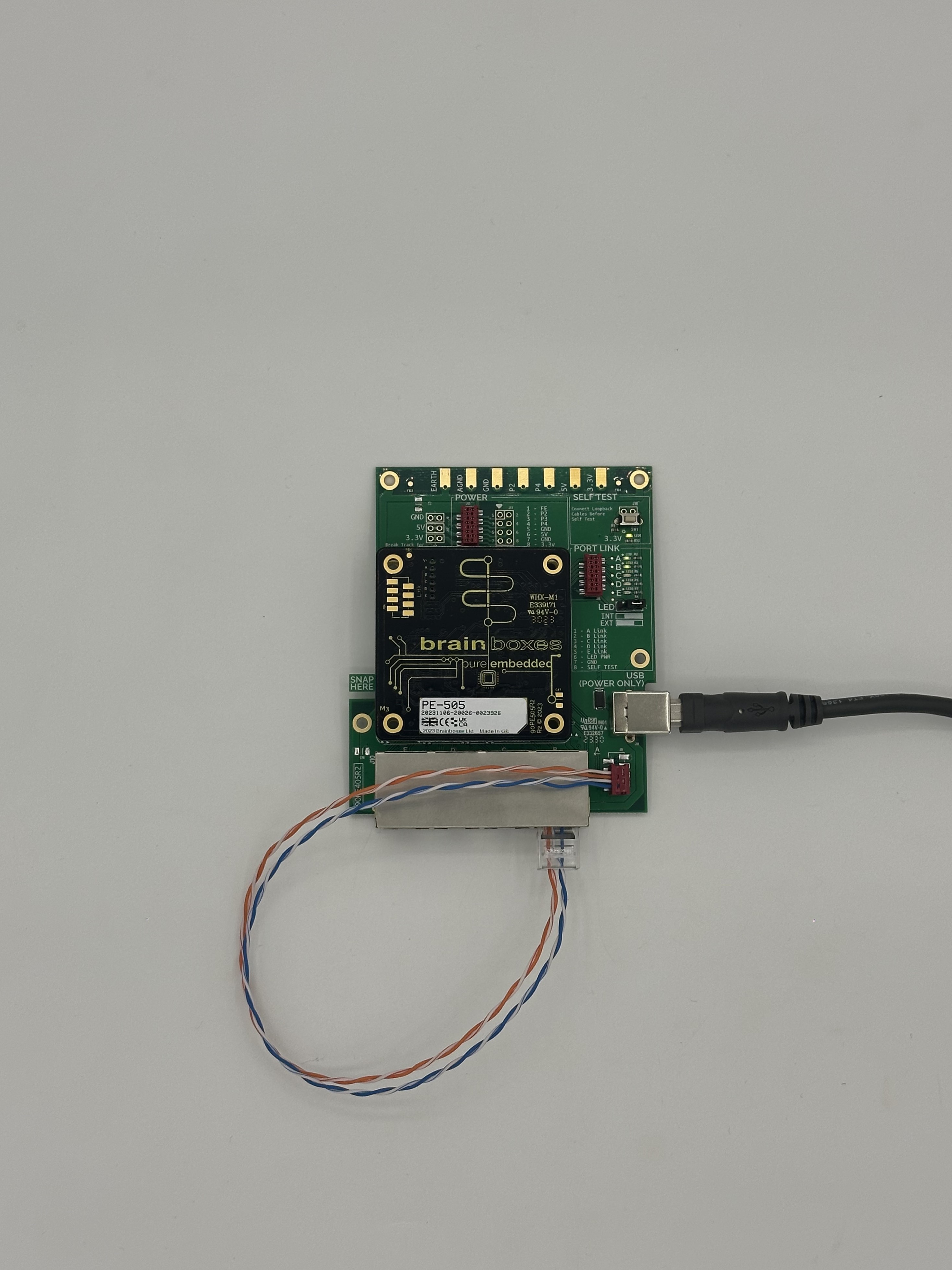
To power your PE-405 evaluation board, connect the included USB-B cable to the evaluation board and your PC/Laptop. You will know that the device is powered up correctly by referring to the LED labelled 3v3 on the evaluation board and the LED labelled V+ on the PE-505 board.
With both LED’s lit, you can continue to test the functionality of the boards. To do this, take the included MicroMatch to RJ45 cable and connect it to the Port A connector on the PE-405 evaluation board. Then take the RJ45 end of the cable and connect it to any of the remaining 4 RJ45 ports.
With your cable connected, locate the ‘Self-Test’ area of the PE-405, where you’ll find a white button. Pressing the button will activate a loopback self-test of ports on the device. For example, if the cable is connected between Port A (MicroMatch) & Port E (RJ45), the associated Port A & Port E LED’s should blink continuously on the Self-Test area of the board.
What is a Broadcast Storm?
When performing the self-test, you must ensure that the board is not connected to your network, if you have the device connected to your network whilst having the switch ports connected to each other, it will cause a network loop, creating a broadcast storm.
A broadcast storm is when an abnormally high amount of broadcast packets are sent out within a short time period, when this happens a networks performance degrades, getting increasingly worse as more and more broadcast packets are being looped around the network loop on the switch, this happens due to the switch’s ports sending out multicast and broadcast traffic that has no endpoint (as the switch is plugged into itself).
Initially, the broadcast storm will likely cause intermittent network connectivity, but very quickly will result in little, if any, network connectivity or result in severe disruption to network endpoints or devices.
PE-405 & PE-505 LED’s
There are multiple LEDs on the PE-405 and PE-505 devices which signify different things.
PE-405
Starting with the PE-405, when you have powered the device up you will notice 1 LED illuminated on the Eval board which indicates that the board is receiving power, you will also notice a smaller LED on the back of the PE-505 indicating that that too is receiving sufficient power.
If you have any network connections or network loops active on the device you will see more LEDs illuminated on both the PE Eval board and the attached PE-505, these LED’s represent what ports currently have an active connection being made to them.
As previously mentioned, when performing a self-test, you will notice extra LEDs illuminated on the device, these LED’s indicate what ports currently have an active connection being made to them, this allows to user to see if the connections they’re attempting to make via the switch are working and that the switch itself is functioning.
PE-505
As mentioned above, there is a single power LED on the PE-505 itself. There are also 5 LED’s labelled A – E for each of the 5 MicroMatch Ethernet ports. When an active connection is made to a port, the LED will illuminate.
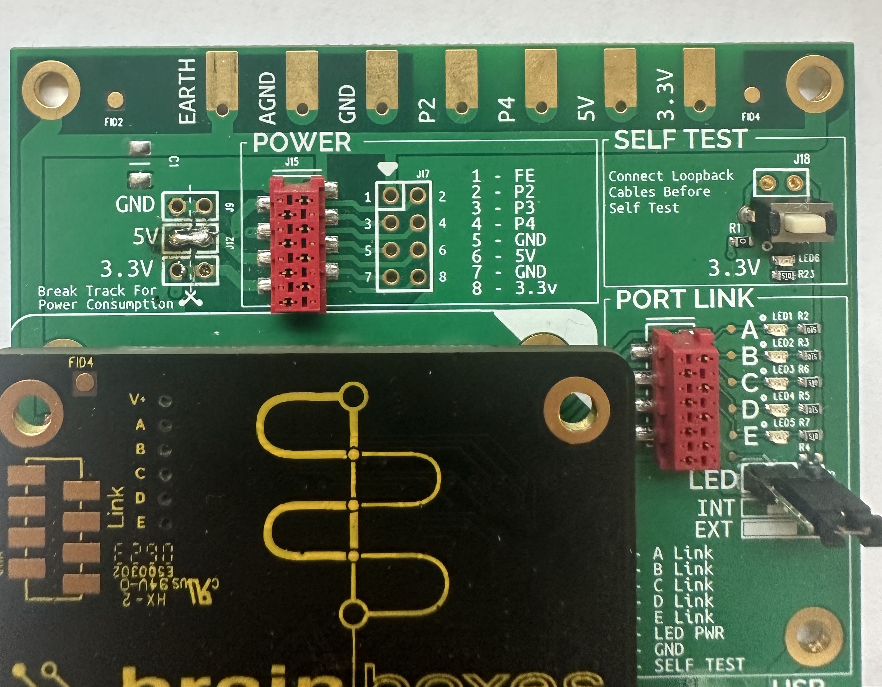
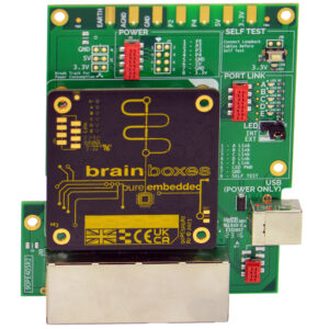
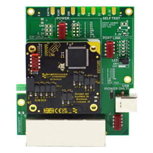
Creating a Test Environment
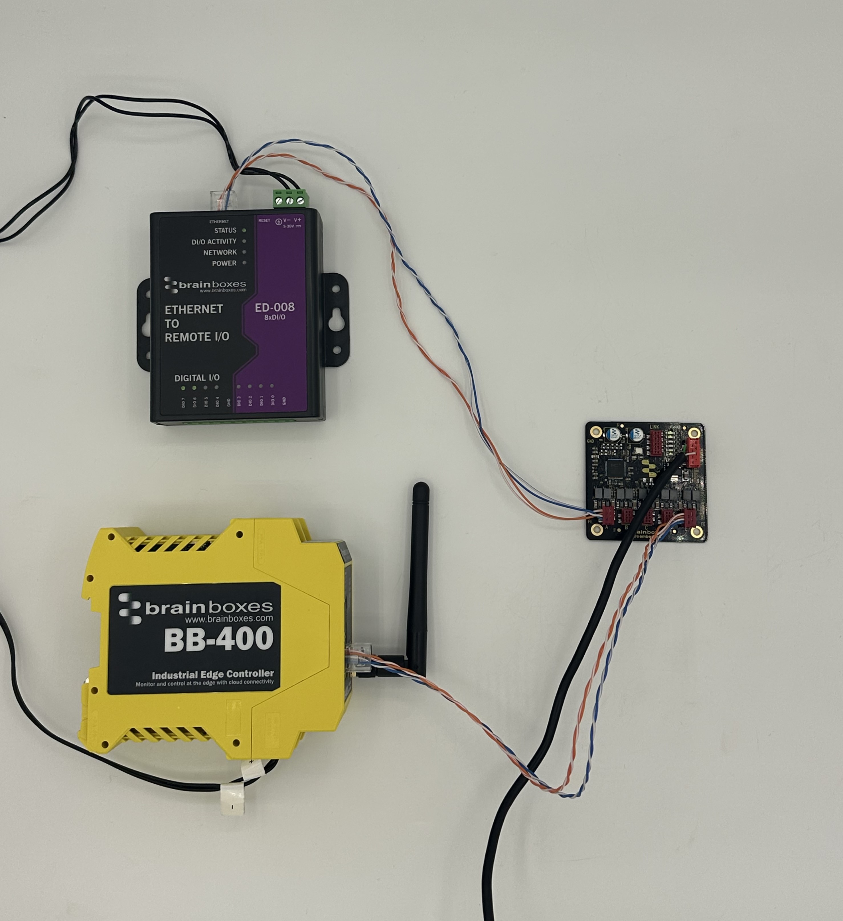
The images below show a small network created using a PE-405 & PE-505. Designed for integration within new or existing systems, it’s compact size and intuitive development path (taking a PE-405 evaluation board, proving functionality, then re-terminating cabling to the MicroMatch connectors of the PE-505) allows for quick transition from proof of concept to deployment environments.
PE-405 Network Test
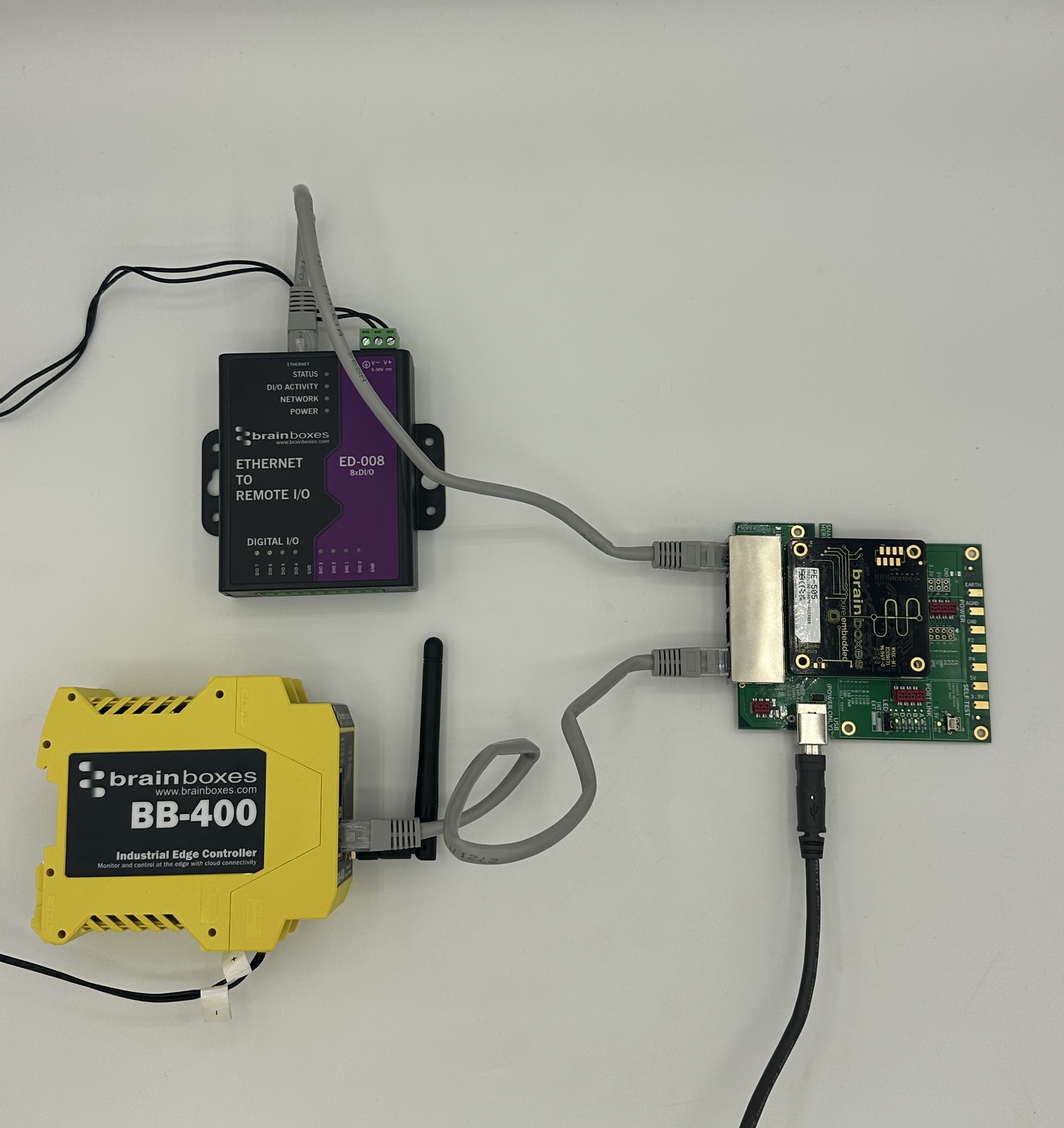
PE-505 Network Test
Monitoring Power Consumption
With the PE-405 eval board there is the functionality available to monitor the power consumption of the board with your devices connected to it.
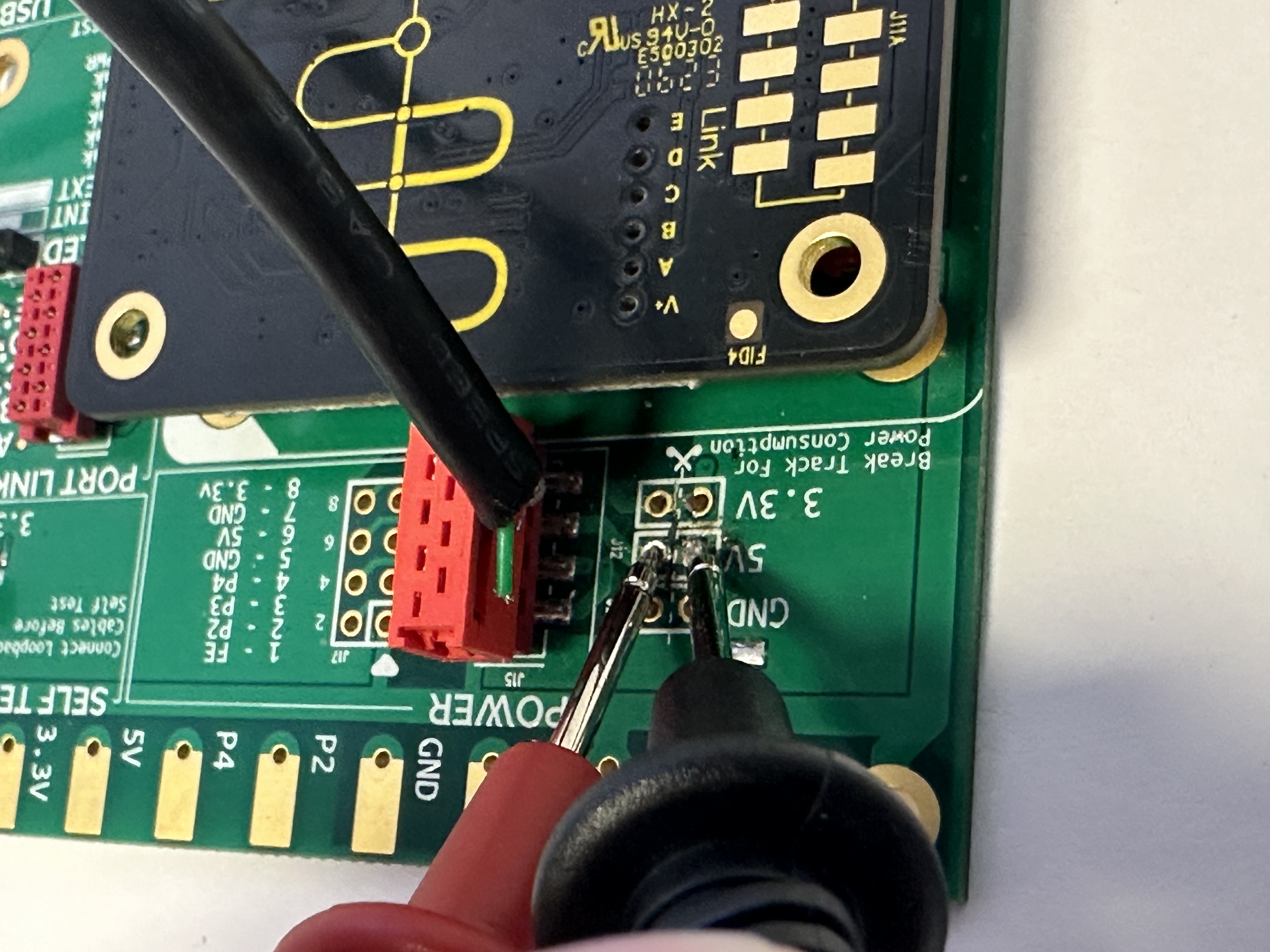
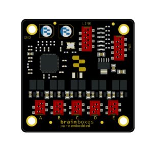
In the ‘Power’ section of the PE-405’s PCB, there is a series of 3×2 traces available for monitoring power consumption (please see ‘B’ in the image below):
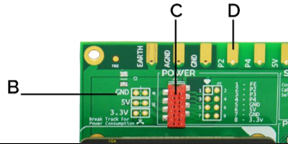
Next to the traces, there is a note of ‘Break Track for Power Consumption’ with a dotted line running down the centre of the 3×2 traces. To monitor the power consumption of your switch, break the track by scratching down the dotted line.
Only Break GND track and measure the current going through this.
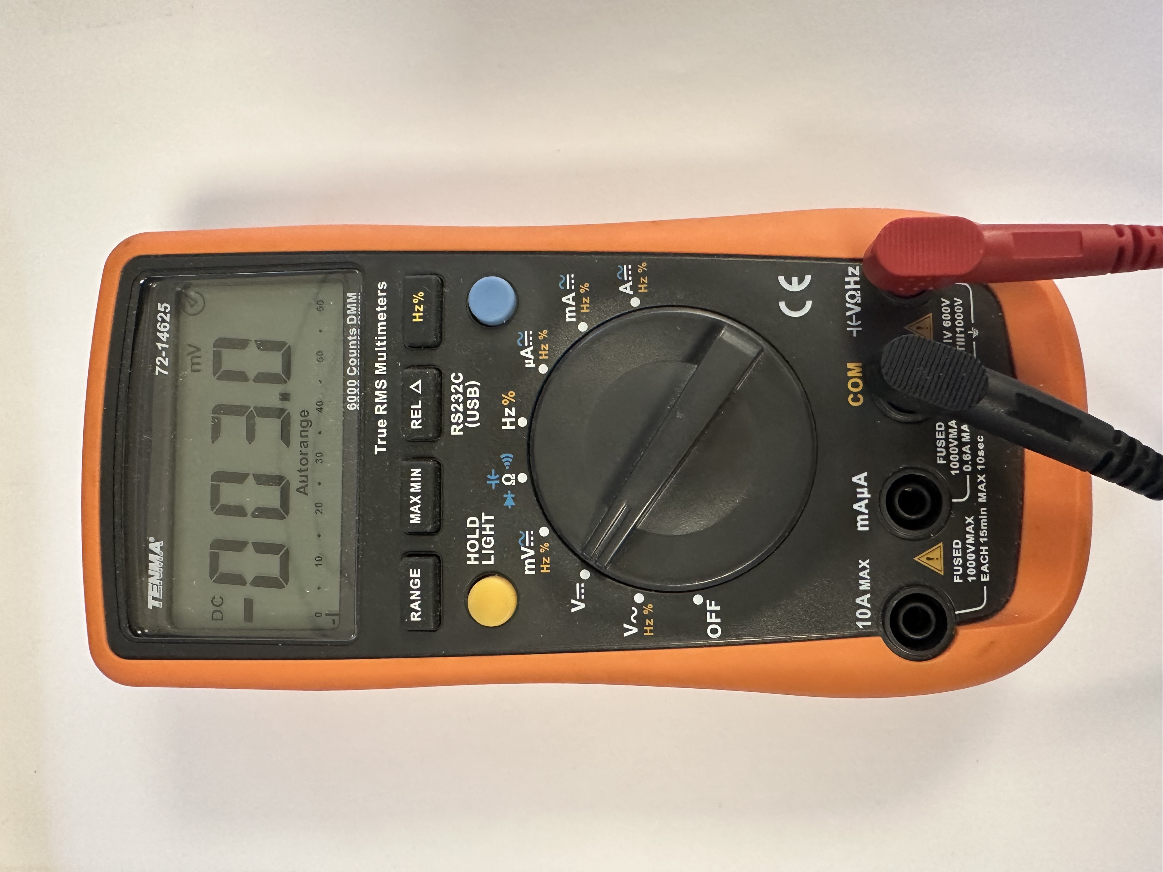
Once the track has been broken, you can use an ammeter to measure the power consumption. Place both probes to either side of the now broken PCB track and a power consumption reading should be available.
By allowing power consumption to be monitored directly, the PE-405 offers a readily available method of confirming power requirements of the switch prior to installation into a system, most beneficial in systems with specific or low power availability.
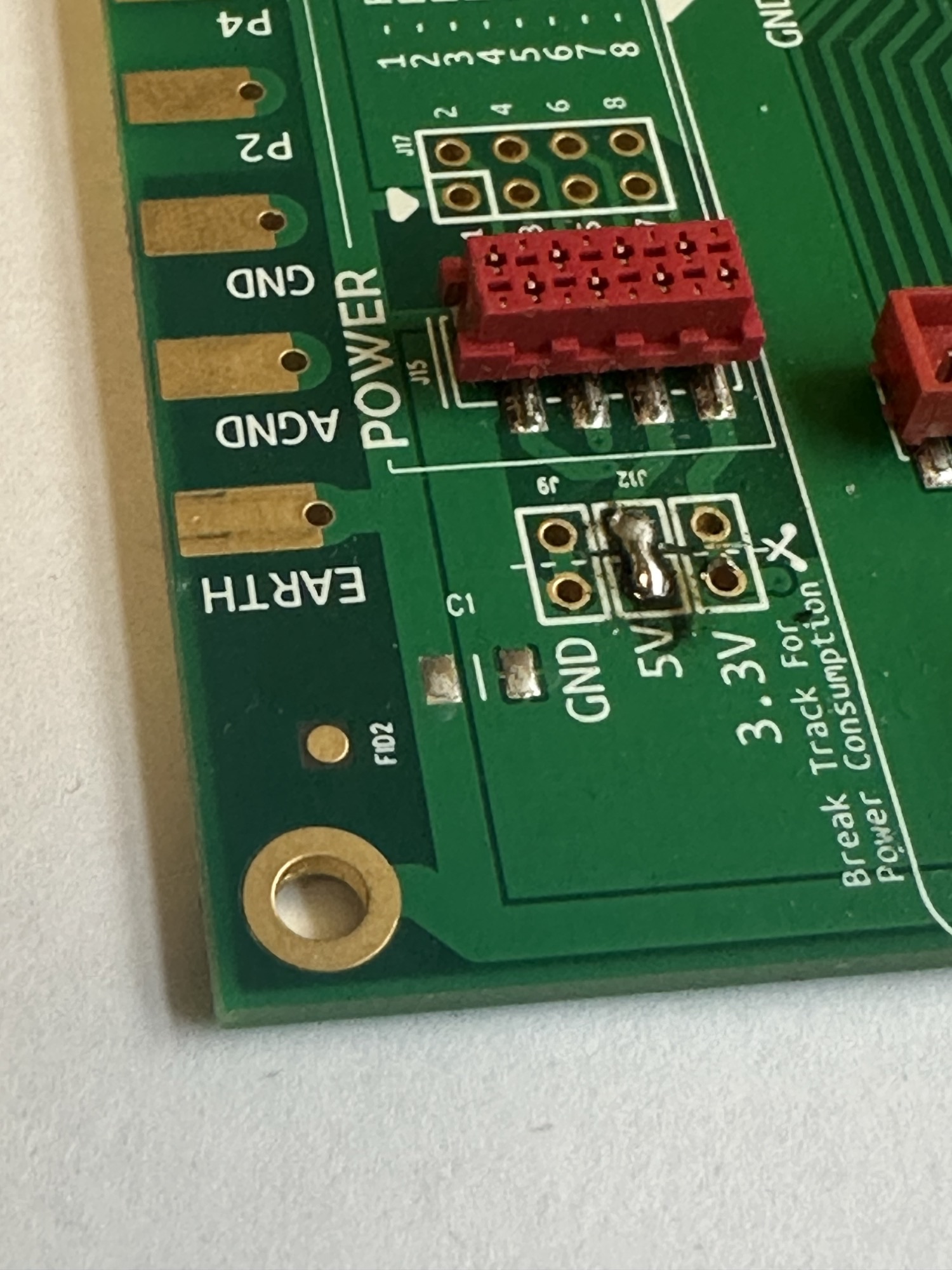
Restoring Power Consumption Track
Because a track has been broken on the PCB for power monitoring, you will need to bridge the connection to allow the device to function as it did prior. The best way to do this is to either use a small blob of solder between the contact points, or solder a small cable into each through hole contact point of the track that was broken.
PE-405 Eval Kit Migration to your System
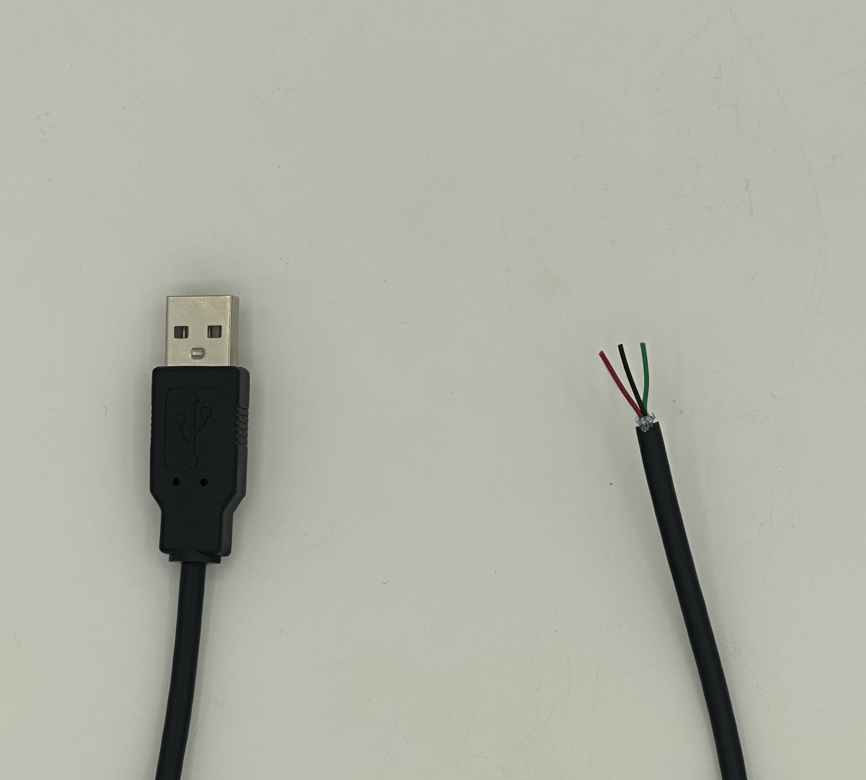
Creating a USB to MicroMatch Power Cable.
The easiest way to power your PE-405/505 is using the provided USB-A to USB-B cable. Or, both devices allow for power to be supplied through a MicroMatch connector on each board exclusively.
To create a USB to MicroMatch power cable, a sacrificial USB cable will be required. For our example below, we’ve used a USB-A to USB-B cable and removed the USB-B terminated end:
To create and correctly terminate your USB to MicroMatch power cable, please see the below table (also available in the PE-405/505 Datasheet) detailing the pinouts of the power connector on both the PE-405 & PE-505:
| PINOUT | 1 | 2 | 3 | 4 | 5 | 6 | 7 | 8 |
|---|---|---|---|---|---|---|---|---|
| POWER | FE | – | – | – | GND | VIN 5v | GND | VIN 3.3v |
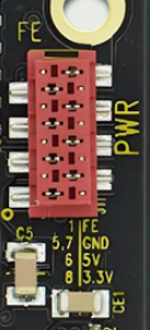
You can also power the PE-405 via crocodile clips on the gold contact pads on the bottom of the Eval board, the contact pads pinouts are as follows:
Warning
When using 5v to power the PE-405 via crocodile clips, ensure that you do not touch the 3.3v contact pad with 5v as this can cause damage to the components on your device.
| EARTH | AGND | GND | P2 | P4 | 5V | 3.3V |
|---|---|---|---|---|---|---|
| Reserved for future function | Reserved for future function | Connect to Negative of PSU | Reserved for future function | Reserved for future function | Connect to 5V power rail | Connect to 3.3V power rail |
The MicroMatch connector is polarised, meaning the cable connector can only mate in one orientation, into the board connector. When wiring, please ensure the correct cables from the USB cable are fastened into the correct pin on the MicroMatch connector.
Now the power cable has been created, you can attach it directly onto the PE-405 evaluation board. Once connected to power, you should see the board illuminate as it did previously when powered through the USB-B connector.
You can also remove the PE-505 from the evaluation board and connect the MicroMatch power cable to the to confirm it is working with the embedded board itself.
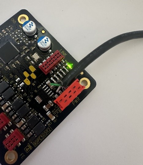
Creating an RJ45 to MicroMatch Ethernet Cable
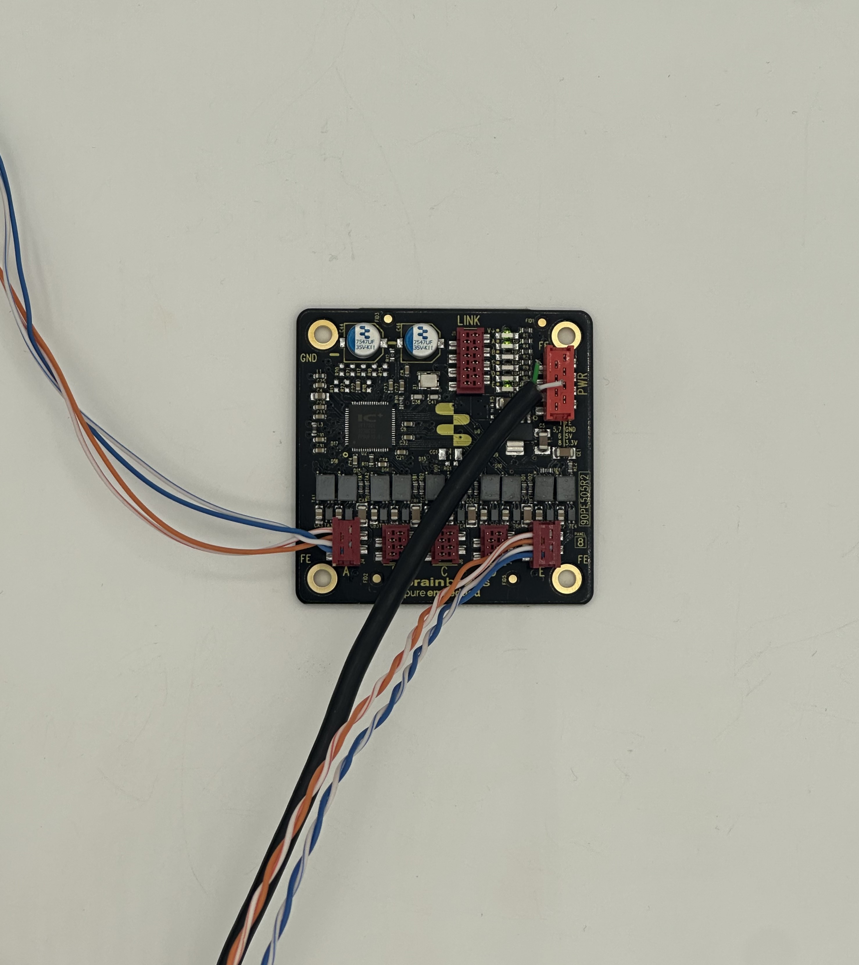
As with the power cable, you can also create your own Ethernet cables, terminating between the MicroMatch connectors of the PE-405/505 and your Ethernet devices, for example, these could be RJ45, M5 or M12.
To create an RJ45 to MicroMatch Ethernet cable, a sacrificial Ethernet cable will be required. Begin by removing one of the RJ45 terminated ends, exposing the inner Ethernet cores. You can then follow the below table (also available in our PE-405/505 Datasheet) to terminate the Ethernet cores into the MicroMatch connector:
External LED States
The PE-405/505 has the ability to extend the onboard LEDs used to provide power & port connectivity state information externally, allowing the user to route these into their enclosure or panel for easier/cleaner viewing, through an external LED.
The user can connect an external LED directly to the LINK MicroMatch header on each board.
Please Note: The output current must be limited through a resistor, allowing a maximum current draw of 20mA @ 3.3V. The LED’s must also be powered through the LED Power Pin.
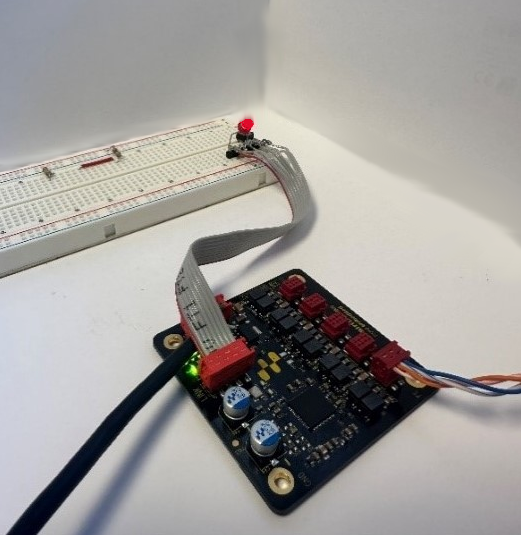
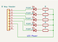
The LED’s function in an active LOW configuration and should be connected as shown in the schematic drawing below.
The power draw of any supplementary LEDs is in addition to the specified power on the datasheet.
If you do not wish to implement electronic based link LED forwarding, there are also holes of ⌀1mm under each of the indication LEDs, which are suitable for housing optical fibres or light pipes of a length less than 50cm.
Now that you have all the cables you need connected to MicroMatch headers, you can now remove the PE-505 from the eval kit, and use it as a standalone embeddable ethernet switch.
Designing the PE-505 into your System
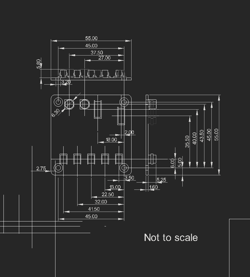
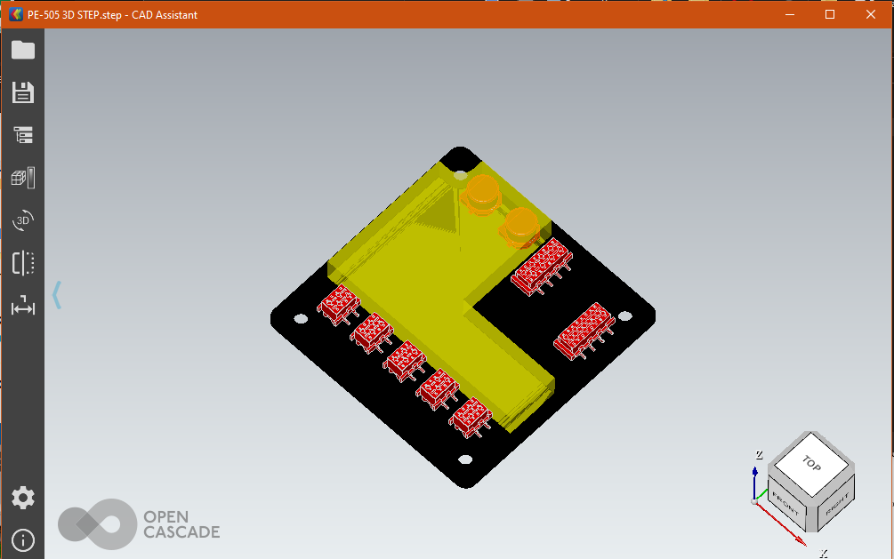
When integrating the PE-505 into your system, our product datasheet provides all the information you’ll require through accurate 2D dimensioned drawings. Also available on our website is a 3D model in the .STEP format, with an included ‘Keep-Out’ area.
For reference, a 3D model is also available for the PE-405 evaluation board. All components within the highlighted Keep-Out area are subject to change. Encroaching into the Keep-Out area should be avoided.
See below for an example of what our 2D & 3D models look like when using a CAD viewing program.
Device Testing & Results
Throughput testing of the PE-505 achieved simultaneous wire speed operation across all 5 ports.
When evaluating the reliability, functionality and power cycling endurance of the PE-505, thorough in-house testing was performed to demonstrate the robustness of the product. Further to this, testing performed by one of our customers over a prolonged period of time illustrated the versatility of the PE-505 under various conditions.
Below is a table of test results showing the length of time a PE-505 run at various temperatures, across various lengths of time. During the tests, Ethernet based devices connected to the PE-505 were continually pinged, with a ‘failure’ classed as a ping request that wasn’t correctly responded to. Further to this, the PE-505 was power-cycled every 30 seconds.
| Temperature (°C) | Time (Hours) | Number of Power Cycles | Failures |
|---|---|---|---|
| 35 | 15 | 1762 | 0 |
| 55 | 4 | 534 | 0 |
| 65 | 2 | 294 | 0 |
| 75 | 17 | 1935 | 1 |
| 85 | 266 | 29700 | 0 |
As shown in the data above, a single failure was observed during testing, further illustrating the robust design of the PE-505 in a wide range of installations, with temperatures varying from 35°C to 85°C, across 304 hours of testing and 34,225 power cycles.
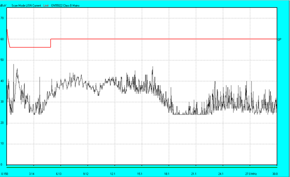
EMC Testing
The PE-505 has been under various Electromagnetic Compatibility (EMC) tests. EMC testing is the regulatory testing of electronic components. EMC is a measure of a devices ability to operate as intended in its shared operating environment whilst, at the same time, not affecting the ability of other equipment within the same environment to operate as intended.
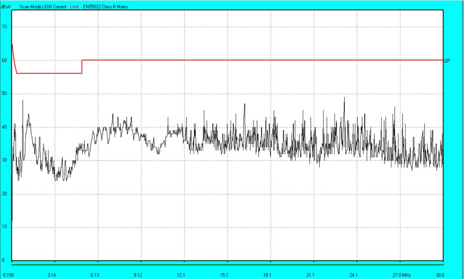
You can find the PE-505’s EMC testing results below:
| 3.3v Positive | 3.3v Negative |
|---|---|
 |
 |
Summary
This has been a guide on the PE-405 & PE-505, showing you from start to finish how to setup and use the device, from unboxing experience to evaluation and complete integration into your own system.
If you have query’s please contact: [email protected] or [email protected]
-
PE-405
$202.50 Add to cart -
PE-415
$202.50 Add to cart -
PE-505
$47.25 Add to cart -
PE-515
$74.25 Add to cart
FAQs